Matchless Tips About What Is 4 * 2 Priority Encoder

Priority Encoder
Decoding the Mystery
1. Unveiling the Logic Behind the Bits
Ever wondered how a system knows which request to handle first when multiple things are clamoring for attention? That's where the 4x2 priority encoder comes in! Think of it as a highly organized traffic controller for digital signals. It's a fundamental component in digital circuits, acting as a translator between multiple inputs and a compressed binary output that indicates the highest priority active input.
Imagine a scenario where you have four different devices all trying to send data to a central processor simultaneously. A simple encoder would just convert these inputs into a binary code. But a priority encoder is much smarter. It doesn't just encode; it prioritizes! It looks at all the incoming requests and identifies the one with the highest assigned priority, then outputs a binary code representing that specific request. So, if input 3 has the highest priority and is active, the encoder will output the binary code for '3', even if other lower-priority inputs are also active. Pretty neat, huh?
So, why is this important? Well, in many digital systems, resources are limited. Only one device can access memory at a time, or only one interrupt can be serviced by the CPU. The priority encoder ensures that the most important requests are handled first, preventing chaos and maximizing efficiency. Think of it like choosing which emergency call to answer first — you wouldn't deal with a stubbed toe before a house fire, right?
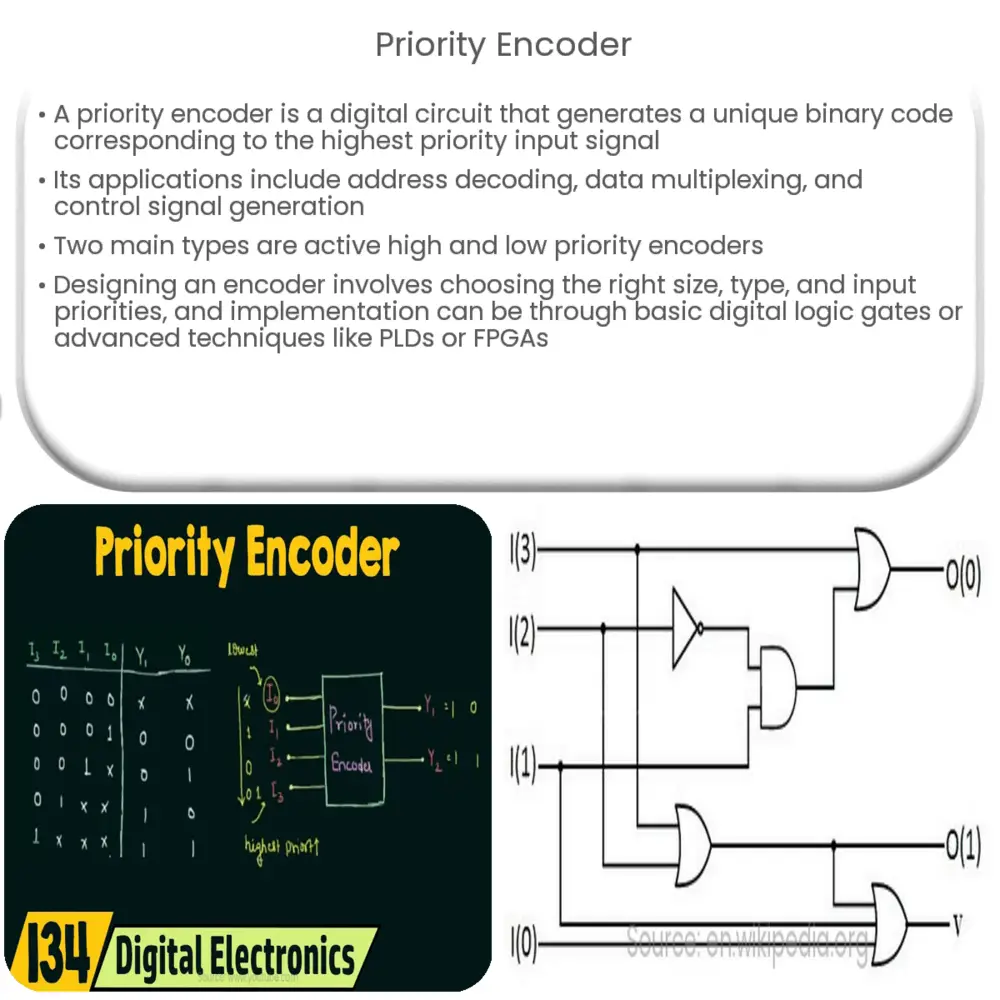
Technically speaking, a 4x2 priority encoder has four input lines (labeled, say, D0, D1, D2, and D3) and two output lines (usually Q0 and Q1). It also often includes a valid output (V) to indicate whether any of the inputs are active. A truth table meticulously outlines the behavior of this little wizard, showing which output corresponds to which priority input. Priority is often assigned from highest to lowest input, so D3 has the highest and D0 the lowest. Let's delve into that truth table a bit later to really solidify our understanding.

Breaking Down the Components
2. The Anatomy of a Priority Selector
Now, lets get a little more technical without getting bogged down in jargon. The inputs of our 4x2 priority encoder, D0 through D3, are the requests or signals coming in. These inputs are typically active-high, meaning a logical '1' represents an active request, and a '0' represents an inactive one. Remember our example from before. Each of these input corresponds to device trying to send data to the main processor.
The outputs, Q0 and Q1, are the binary representation of the highest priority active input. If D2 is the highest priority active input, then the outputs Q1 and Q0 will be '1' and '0' respectively, which together form binary '10' which is the code for 2. Don't forget the valid output, V! This output is crucial because it tells you whether any of the inputs are active. If V is '0', it means all inputs are inactive, and the outputs Q0 and Q1 are meaningless (often set to '0' by convention). Without V, you wouldn't know if the outputs are actually representing a valid priority.
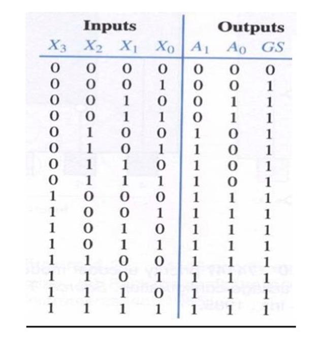
The truth table is the key to understanding how the 4x2 priority encoder works. It's basically a map that shows all possible input combinations and their corresponding outputs. A typical truth table for a 4x2 priority encoder will prioritize the highest-numbered input. For example, if D3 is active (1), the outputs Q1Q0 will be 11 (binary 3), regardless of the state of D2, D1, or D0. If D3 is inactive (0) and D2 is active (1), then Q1Q0 will be 10 (binary 2), and so on. The 'X' in the truth table typically represents a "don't care" condition, meaning the output is the same regardless of whether the input is a 0 or 1. This simplifies the logic and reduces the number of gates required to implement the encoder.
In essence, the truth table provides a concise and unambiguous definition of the encoder's behavior. By studying the truth table, you can easily determine the output for any given set of inputs, which is invaluable for designing and troubleshooting digital circuits that use priority encoders.

Real-World Applications
3. Beyond the Theory
So, where do these priority encoders actually show up in the real world? They're surprisingly common, often hidden behind the scenes in the electronic devices we use every day. One prevalent application is in interrupt controllers within microprocessors and microcontrollers. Interrupts are signals that tell the processor to stop what it's doing and handle a more urgent task. A priority encoder ensures that the most important interrupt is serviced first.
Consider a computer system. Various peripherals like the keyboard, mouse, hard drive, and network card can all generate interrupts. The interrupt controller uses a priority encoder to determine which interrupt to handle based on its assigned priority level. For instance, a hard drive error might have a higher priority than a keyboard input, ensuring that data loss is prevented before user input is processed.
Another common application is in keyboard scanning. When you press multiple keys on a keyboard simultaneously, the keyboard controller uses a priority encoder to determine which key press to register first. This prevents ambiguity and ensures that the correct characters are entered. It might not seem like much, but imagine the chaos if your keyboard randomly registered key presses when you hit multiple keys at once!
Priority encoders are also used in data acquisition systems, where multiple sensors are monitoring different parameters. The encoder can prioritize the readings from the most critical sensors, ensuring that important data is processed first. Furthermore, they find applications in bus arbitration, where multiple devices are competing for access to a shared bus. The priority encoder determines which device gets access to the bus based on its priority, preventing conflicts and ensuring efficient data transfer. From factory automation to medical equipment, priority encoders are silently working to keep things running smoothly and efficiently.

4 To 2 Encoder Truth Table And Circuit Diagram » Wiring & Schematic
Building Your Own
4. From Concept to Circuit
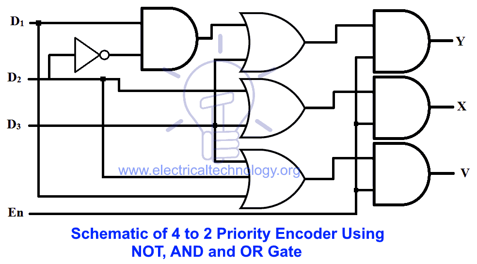
Now for the fun part: how do you actually build a 4x2 priority encoder? While integrated circuits (ICs) containing pre-built priority encoders are readily available (like the 74LS148), understanding the underlying logic is crucial. The implementation typically involves a combination of AND gates, OR gates, and NOT gates, strategically arranged to achieve the desired priority encoding. Let's break down the logical expressions and then discuss how to translate that into a circuit.
Recall that the outputs Q1 and Q0 represent the binary code of the highest-priority active input. So, Q1 should be '1' if either D3 or D2 is the highest-priority active input. Q0 should be '1' if either D3 or D1 is the highest-priority active input. The valid output V is simply '1' if any of the inputs are active. Translating this into Boolean algebra, we get the following expressions:
Q1 = D3 + (D2 !D3)
Q0 = D3 + (D1 !D3 !D2)
V = D0 + D1 + D2 + D3These equations can be directly implemented using logic gates. The exclamation mark (!) represents logical NOT. So, !D3 means "NOT D3". A practical implementation would involve using AND gates to combine the inputs according to the Boolean equations and then using OR gates to combine the outputs of the AND gates. You can also use a Karnaugh map to simplify the logic and potentially reduce the number of gates required. However, the direct implementation from the Boolean equations above is often the most straightforward to understand.
Troubleshooting Tips and Tricks: Ensuring Your Encoder Works Perfectly
5. When Things Go Wrong: Practical Troubleshooting
So, you've built your 4x2 priority encoder, but it's not behaving as expected. Don't panic! Troubleshooting digital circuits is a common part of the design process. Here are some tips and tricks to help you diagnose and fix the issue. The most important tool you will have is your DMM (Digital Multi Meter) and logical thinking.
First, double-check your wiring. A loose connection or miswired gate can cause all sorts of problems. Use a multimeter to verify that all the connections are solid and that the correct voltages are being applied to the IC. Make sure you are getting the proper voltages at each input and output.
Next, verify your truth table. Systematically apply each input combination and check the corresponding output. If the output doesn't match the expected value in the truth table, trace the signal path through the circuit to identify the faulty gate or connection. Use a logic probe or oscilloscope to examine the signals at different points in the circuit.
Finally, consider the possibility of a faulty IC. While rare, it's not impossible for an IC to be defective. If you've exhausted all other troubleshooting steps, try replacing the IC with a known good one. Also, ensure the power supply provides a stable and clean voltage. Voltage fluctuations or noise can cause unpredictable behavior in digital circuits. One tip to prevent this, consider a filtering capacitor, that will remove noise or voltage fluctuations. By following these steps, you can systematically identify and resolve most common problems with 4x2 priority encoders.
FAQs About 4x2 Priority Encoders
6. Your Burning Questions Answered
Still have some lingering questions? Let's tackle some frequently asked questions about 4x2 priority encoders.
7. Question 1: What's the difference between a regular encoder and a priority encoder?
A regular encoder simply converts an active input into a binary code. A priority encoder, on the other hand, prioritizes the inputs and outputs the binary code of the highest-priority active input, ignoring the other active inputs.
8. Question 2: Can I cascade multiple 4x2 priority encoders to create a larger encoder?
Absolutely! You can cascade multiple 4x2 priority encoders to create encoders with more inputs. The output of one encoder becomes the input to another, and you'll need to add some additional logic to handle the priority between the different encoders.
9. Question 3: What happens if two inputs with the same priority are active?
This is a tricky scenario! Typically, priority encoders are designed with a specific priority order. If two inputs with the same priority are active simultaneously*, the encoder will usually output the code corresponding to the higher-numbered input (e.g., if D2 and D3 have the same priority and are both active, D3 will be encoded). However, this behavior depends on the specific design and implementation of the encoder, so it's important to consult the datasheet for the particular IC you're using.

